04. Controlling simple devices
Arduino is an open-source microcontroller platform that, when combined with the Firmata firmware, can be used to easily control a variety of devices using its analog and digital output ports.
Anything that can be controlled using TTL pulses will work, and there are also other devices and more specialized sensors that you can integrate. We published instructions on how to build some of these devices at our Maze Hardware site.
This tutorial will require some hardware tinkering and a bit of coding in Syntalos to be useful, so it is for intermediate users.
1. Prepare your Arduino
Open your Arduino IDE. The navigate to Sketch → Include Library → Manage Libraries. Search for Firmata and install the “Firmata by Firmata Developers” item.
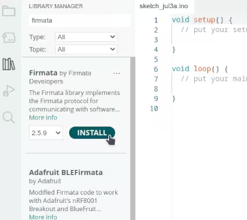
Then, navigate to File → Examples → Firmata, and select the Firmata variant you want. Standard Firmata is the option we select here.
The Firmata code for Arduino opens in a window, and you can upload it to your device the usual way. The Arduino is now ready to be used, so let’s test it!
2. Set up Syntalos
Create a new Syntalos project and add a Python Script, Firmata User Control, Firmata IO and Table module.
Enter the settings of the Python module and edit its ports. Add a firmata-in input port with input data
type FirmataData and an output port of type FirmataControl named firmatactl-out.
You can also add an output port of type TableRow named table-out for later use.
The we create some boilerplate code for the Python module, which does nothing, for now:
import syntalos_mlink as syl


fm_iport = sy.get_input_port('firmata-in')
fm_oport = sy.get_input_port('firmatactl-out')
tab_oport = sy.get_input_port('table-out')


def prepare() -> bool:
    """This function is called before a run is started.
    You can use it for (slow) initializations."""
    return True


def start():
    """This function is called immediately when a run is started.
    This function should complete extremely quickly."""
    pass


def stop():
    """This function is called once a run is stopped."""
    pass
To play around with Firmata manually, without using the script yet, we connect input and output of Firmata User Control to the respective ports of Firmata IO:
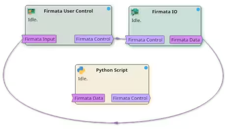
Open the settings of Firmata IO and select the serial port number of your plugged-in Arduino.
dialout group to use serial devices.
In order to do that, open a terminal and enter sudo adduser $USER dialout, confirming with
you administrator password. After a reboot / relogin, connecting to your Arduino should work now.3. Manual work
Before automating anything, we want to run some manual tests first and control our Arduino by hand. For testing purposes, we wire up an LED to one of its free ports. We can then already hit the Ephemeral Run button of Syntalos, to start a run without saving any data.
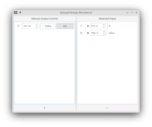
Double-click on the Firmata User Control module to bring up its display window. There, you can read
inputs and write to outputs. Click on the Plus sign to add a new Menual Output Control and add
a digital output pin.
On the Received Input side, select an analog, or digital input. Select the Arduino pins that you want to read
or write from, and change the values of your output.
The Arduino should react accordingly, and also display the read input values.
This is pretty nice already, but we do want to automate this, so Syntalos can change values automatically, for example based on test subject behavior, and also write the data it reads to a file for later analysis.
4. Automation: Blinking light
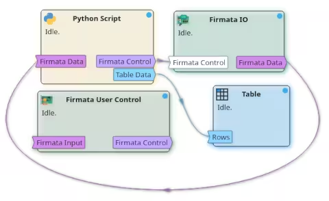
To automate things, we need to go back to the Python script again. First, we need to break the port connections between Firmata User Control and Firmata IO (select them with a click, and then push the Disconnect button), and instead connect the ports to the respective Python Script ports:
For demonstration purposes, we will let an LED blink at a given interval first, and log the time when we sent the command to get the LED to blink.
This is the code we need to achieve that:
| |
Initially, in line 10, we need to fetch references to our input/output ports (using only the latter for now), so we
can use them in later parts of the script. The prepare() function is called before the experiment run is actually started.
In it we can set metadata on our respective ports. In our case we set a table header using the table_header property on the
table row output port, and also suggest a name to save the resulting CSV table under using the data_name_proposal property.
Then, once the experiment is started, we can actually send messages from our module to other modules. In the start() routine,
we first register pin 8 on the Arduino as digital output pin (adjust this if your LED is on a different pin).
This example uses convenience methods to handle digital pins. For example, the call to
firmata_register_digital_pin() on the Firmata control port could also be written as:
ctl = syl.new_firmatactl_with_id_name(syl.FirmataCommandKind.NEW_DIG_PIN, 8, 'led1')
ctl.is_output = True
fm_oport.submit(ctl)
Not every action has convenience methods, but the most common operations do.
Then, we launch our custom function trigger_led_pulse() where the actual logic happens to make the LED blink.
In it, we send a new table row to the Table module for storage & display, using the syl.time_since_start_msec() function
to get the current time since the experiment run was started and naming the event led-pulse. You should see these two values
show up in the table later. Then, we actually send a message to the Firmata IO module to instruct it to set the LED pin HIGH
for the time LED_DURATION_MSEC.
To introduce some delay before sending another such command, we instruct the trigger_led_pulse() function to be called again
after LED_INTERVAL_MSEC via syl.schedule_delayed_call(LED_INTERVAL_MSEC, trigger_led_pulse).
This is repeated until the experiment has been stopped by the user.
If you hit the Run button, the experiment should run and the LED should blink for 250 msec every 2 sec.
5. Automation: Reading Data
Now, let’s read some data and let an LED blink for each piece of data that was received! We assume you have a switch placed on one Ardino pin, and an LED on another for testing purposes.
The code we need for this looks very similar to our previous one:
| |
In start() we now additionally register pin 7 as an input pin this time.
We also need to read input from our Firmata device now, for which we registered fm_iport as input port.
Every input port in Syntalos’ Python interface has a on_data property which you can assign a custom function to,
to be called when new data is received. We assign our own on_new_firmata_data() function in this example.
In on_new_firmata_data(), we first check if the received data is valid (it may be None to signal that a run
is being stopped right now). Next, we check if we have data from the right pin by checking if it is is digital and
if it is the pin that we previously labelled “switch”. We ignore any other data (there should not be any, but just in case…).
Then, if we receive a True value, we command the LED to blink for half a second and log that fact in our table, otherwise
we just log the fact that the switch is off.
Upon running this project, you should see the LED flash briefly once you push the button, and see the state of the button logged in the table displayed by the Table module.
6. Expansion
With this, you have basic control over a lot of equipment to control behavior experiments, from TTL-controlled lasers, to gates and lick sensors. Try making this work with your hardware, try some DIY Maze Hardware or hardware from other open source projects to make behavior experiments work.