SpikeGLX Remote

This module controls a SpikeGLX Neuropixels recording that runs on another computer, through SpikeGLX’s Remote Command Server.
It starts and stops the SpikeGLX run in lockstep with the Syntalos run, names the SpikeGLX file-set after
the Syntalos recording, writes Syntalos provenance (collection ID, subject, start time) into SpikeGLX’s .meta
files, continuously logs how the SpikeGLX sample counters relate to the Syntalos master clock, and can optionally
stream live data from any SpikeGLX stream (IMEC probes, OneBox, NI-DAQ) into Syntalos.
The full, authoritative recorded neural data itself stays on the SpikeGLX computer. The Syntalos module records where the files were written instead (see Output Data Format).
Prerequisites on the SpikeGLX side
- Enable the Command Server in SpikeGLX (
Options ▸ Command Server Settings…) and make sure the port (default4142) is reachable from the Syntalos computer. - Click Enable Remote Command Server and then click My Address, note the IP address for Syntalos.
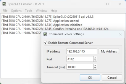
- Run parameters must be validated once per SpikeGLX launch (click Detect and Verify | Save in the acquisition configuration). If you enter the devices to select in the module settings, the module performs this step remotely whenever SpikeGLX reports unvalidated parameters, so you do not have to click Detect after launching SpikeGLX.
- Unless you use the Monitor mode, keep SpikeGLX’s Gates-tab option Show enable/disable recording button enabled with initially disabled (the SpikeGLX default). The module starts acquisition while Syntalos prepares the run and only enables file writing at the moment the Syntalos run starts.
Usage
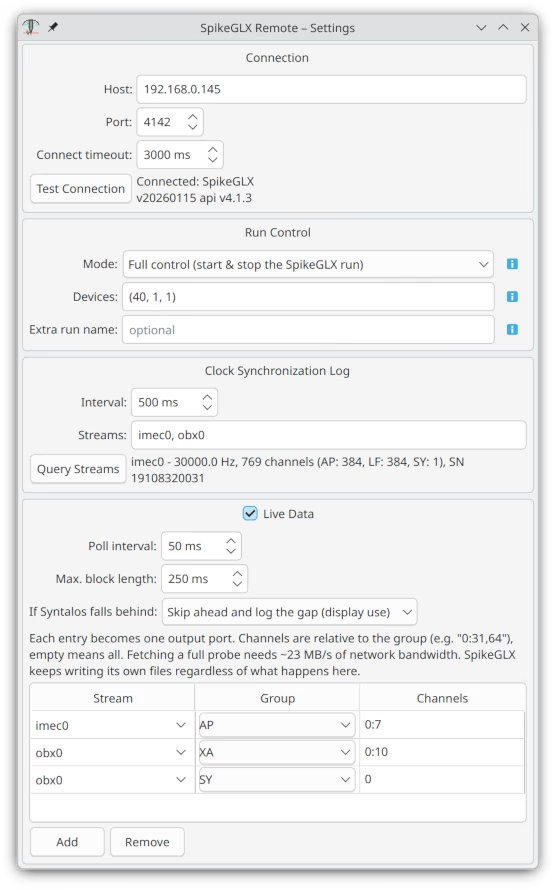
The settings dialog has four groups:
- Connection — host and port of the SpikeGLX computer and a connect timeout. Test Connection shows the SpikeGLX version and the probe list. Provide it with the IP and port you set in SpikeGLX on Windows. Make sure the Windows and the Syntalos computer are connected to the same network.
- Run Control — the mode, the devices to select and the run-name template:
- Automatic (default): behaves like Full control if SpikeGLX is idle, and like Gate only if a SpikeGLX run is already in progress. Only a run that Syntalos started is stopped again at the end.
- Full control: Syntalos starts the SpikeGLX run during preparation, enables recording at run start, disables it at run end and stops the SpikeGLX run. SpikeGLX must be idle.
- Gate only: you start the SpikeGLX run yourself (with recording disabled); Syntalos only enables and disables recording. Use this if SpikeGLX needs a long time to spin up, or you want to watch signals before the experiment starts.
- Monitor: Syntalos never changes SpikeGLX’s state, it only logs sample counts and fetches live data.
- Devices: e.g.
(40,1,1)for a probe in slot 40, port 1, dock 1,(21,obx)for a OneBox in slot 21 or(nidq)for NI-DAQ; several entries can be combined. When set, the module remotely performs Detect and Verify | Save with exactly these devices if SpikeGLX has not validated its parameters yet. - Extra run name: the SpikeGLX run (file-set) name is generated automatically as
<yyyyMMdd>_<subject>_<experiment>_<collection-tag>, e.g.20260830_TestSubject_MM-1_de5b737f, with unavailable parts left out. The collection tag is the short fragment of the Syntalos collection ID, so the SpikeGLX files can be matched to the Syntalos recording directly. The optional extra name is appended, which is useful when one Syntalos instance controls several SpikeGLX rigs. Characters SpikeGLX does not permit are automatically replaced.
- Clock Synchronization Log — which streams’ sample counters are logged against the Syntalos master
clock, and how often. Use Query Streams to see what SpikeGLX offers (
imec0,obx0,nidq, …). - Live Data — enable polling of stream data into Syntalos output ports. Each entry selects a stream, a
channel group (
AP,LForSYfor probes,XA,DW,SYfor OneBox,MN,MA,XA,DWfor NI-DAQ, orALL) and an optional channel subset relative to that group, e.g.0:31,64. Every entry becomes one output port, so ports exist even while SpikeGLX is offline and connections in the graph are kept. For the digital groupsSYandDWthe subset selects lines instead of channels — see Digital lines below — so6picks just the imec sync waveform.
Fetching a complete 384-channel AP band at 30 kHz needs roughly 23 MB/s of network bandwidth; select channel subsets when streaming more than one or two probes. If Syntalos falls behind selects what happens when live data was overwritten in SpikeGLX’s ring buffer before it could be fetched: either abort the run (the default, for when the live data must be complete, e.g. because it is recorded with the Zarr Writer), or skip ahead to the newest data, log a warning and count the gap in the dataset attributes (the right choice when the Syntalos side is only used for display). The files SpikeGLX writes are never affected by this.
Run provenance
Every run exchanges provenance information with SpikeGLX. Syntalos writes sy_collection_id, sy_subject_id,
sy_subject_group, sy_experiment_id, sy_run_name, sy_module_name and sy_instance_id (identifying the
controlling Syntalos instance) into the .meta files of the SpikeGLX file-set, plus sy_ephemeral_run for
temporary runs, and copies SpikeGLX’s complete parameter set into the Syntalos dataset attributes as
spikeglx_params.
This keeps runs comparable with each other later on. The metadata is sent immediately before the run starts.
The Syntalos-side start time is found via sy_collection_id in the collection’s own metadata.
In Monitor mode Syntalos never writes anything to SpikeGLX, so the .meta files stay untouched.
SpikeGLX keeps these keys for the rest of its own run and writes them into every file-set it closes, so the
module blanks them again once the Syntalos run is over. A file-set recorded afterwards — in Gate only mode,
where the SpikeGLX run outlives the Syntalos one — therefore carries empty sy_* entries instead of claiming
to belong to this Syntalos run.
Wiring example
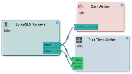
Here two live-data entries were configured, imec0/AP and imec0/SY, which is why the module shows
the two output ports imec0 AP and imec0 SY. The AP band goes to a Zarr Writer
that is set to the Int16 Signals input type, so the samples are stored exactly as SpikeGLX acquired them,
and to a Plot Time Series module for live display. The SY port carries
line events rather than samples, so it goes to a Digital Lines plot port (and, if the
edge times should be recorded, to a Zarr Writer set to Line Readings).
Note that none of this is needed to record the probe: SpikeGLX writes its own files regardless of whether any live-data entry is configured at all.
Time Synchronization
SpikeGLX keeps its own time base: a sample counter per stream that starts with the SpikeGLX run. This module
relates that counter to the Syntalos master clock by repeatedly asking SpikeGLX for the current sample count
and timing the request (the reference point taken at run start, the pairs in the .tsync file, and the
counter synchronizer that timestamps live data all work this way). Live data is therefore timestamped by
sample index (time_unit = "index" with sample_rate), anchored to the master clock, in the same way the
Open Ephys AcqBoard module works.
Accuracy of the absolute time alignment between SpikeGLX and Syntalos
A sample is digitized on the probe, buffered by the acquisition hardware and its driver, fetched by SpikeGLX and appended to its stream buffer, and only then does the sample counter advance. A request for that counter additionally waits for SpikeGLX’s GUI thread and travels over the network. The network round-trip delay can be measured and removed, but the buffering ahead of the counter is invisible to Syntalos. The result is a constant offset of unknown size (typically 20–100 ms, depending on hardware, SpikeGLX load and network) by which all SpikeGLX samples appear later in Syntalos time than they were actually acquired.
This does not affect relative timing: the offset is nearly constant, so sample rate and clock drift are determined precisely over the course of a run, and intervals within the SpikeGLX data are exact.
Precise multi-device time alignment
For sub-millisecond alignment between the SpikeGLX and Syntalos computers, record a shared hardware signal
in both systems: e.g. SpikeGLX’s own sync square wave (recorded in the SY bit of every stream and available
at the base station / OneBox output) captured by a Syntalos-timestamped digital input, or a Syntalos-controlled
TTL pulse fed into a SpikeGLX XA or DW channel.
The edges present in both recordings then give the exact offset; use the sample-count log described below
to convert between sample indices and master time once the offset is known.
The recording gate opens only after the Syntalos run has started, because SpikeGLX must receive the command
from this module. The record_start_master_time_us attribute records when the command was issued; SpikeGLX
then still needs to create its file-set, so the first few tens of milliseconds of the run are usually not
contained in the SpikeGLX files.
Output Data Format
The module’s dataset contains:
<stream>-samplecount.tsync— a continuous time-sync file per selected stream with pairs of SpikeGLX sample count and Syntalos master time (µs), taken at the configured interval. These pairs carry the systematic offset described in Time Synchronization: use them for sample rate, drift and coarse alignment, and a shared hardware signal for the exact offset.attributes.toml— SpikeGLX version, the stream layout (channel counts per group, sample rates, serial numbers), the run name, the master-clock times at which recording was enabled and disabled, reference points (sample count ↔ master time) per stream, live-data statistics, and the location of the recorded files on the SpikeGLX computer:remote_data_dir,remote_run_dir,remote_file_prefix,remote_filesand the gate/trigger indices.
Analog live data ports publish SignalBlockI16 with the raw signed 16-bit sample values, exactly as
SpikeGLX acquires them. The metadata keys data_unit, data_scale and data_offset convert them to
volts, signal_names lists the channels (AP0, AP1, …), and the spikeglx_* keys identify the stream,
channel group and absolute channel indices, see
Common Stream Metadata.
Digital ports publish LineReading events instead, see Digital lines.
Digital lines
The digital groups SY (probe and OneBox status word) and DW (NI-DAQ and OneBox digital lines) are not
channels: SpikeGLX packs their lines into 16-bit words, with the lowest numbered line in the lowest order
bit. A line is therefore numbered
lineIdx = word * 16 + bitwhich is exactly the numbering SpikeGLX itself uses in its Sync and trigger settings. The Channels
field of a live-data entry takes these line numbers for SY and DW entries, so 6 selects the imec sync
waveform and an empty field selects every line of the group. Only the words that actually contain a
selected line are fetched.
Rather than a full-rate stream of packed words, these ports publish LineReading events: one event
whenever a selected line changes level, plus one per line at the start of the run so its initial level is
known. A 1 Hz sync waveform therefore produces two events per second instead of 30 000 samples, and the
edge times are what matters anyway — the raw word is already in SpikeGLX’s own files at full rate. The
events carry time_unit = "microseconds" on the Syntalos master clock, data_unit = "ttl",
is_digital = true, and spikeglx_lines listing the published line numbers. They can be recorded by the
Zarr Writer and JSON Writer modules, displayed by
Plot Time Series, and fed to any module taking line readings.
The bits of an imec probe’s SY word have fixed meanings:
| Line | Meaning |
|---|---|
| 0 | Acquisition start trigger received |
| 2 | COUNT error (communication) |
| 3 | SERDES error (communication) |
| 4 | LOCK error |
| 5 | POP error (internal buffer overflow) |
| 6 | Sync waveform — this is the line to use for alignment |
| 7 | SYNC error — a communication error, not the sync waveform |
| 11 | MISS — this sample was zero-filled by SpikeGLX to replace a lost one |
The remaining bits are unused. Quad-base probes (NP2020) record four SY words, one per shank, so shank
k’s sync waveform is line k * 16 + 6; every other probe type has a single SY word. A OneBox DW
word carries its 12 thresholded analog channels on lines 0–11. For NI-DAQ, the line number is the same
bit #N that the SpikeGLX manual tells you to enter in a trigger setup, counting across both devices.
See also: SpikeGLX Metrics Help
Selecting the ALL group is unaffected by any of this: it dumps every acquired channel of the stream,
digital words included, as a signal block.
Ports
| Name | Direction | Data Type | Description |
|---|---|---|---|
| Out | SignalBlockI16 | One port per analog live-data entry, e.g. imec0 AP (imec0-ap) | |
| Out | LineReading | One port per digital (SY, DW) live-data entry, e.g. imec0 SY (imec0-sy) |