Signal Filter

The “Signal Filter” module applies a chain of IIR filters (high-/low-pass, band-pass, band-stop, notch or custom) to incoming signal-block data in real time, and forwards the filtered signal on its output port.
It is useful for, e.g., removing mains hum or extracting a frequency band of interest (such as the local field potential or spike band of an electrophysiology recording) from a signal before it is recorded or plotted further downstream.
Internally, this module uses the iir1 library to apply the selected filters.
Usage
The module accepts a single signal stream and produces a single filtered stream of the same type. Both the input data type and the filter chain are configured in the settings window.
Input type
Because Syntalos signal blocks are strongly typed, you first have to choose which kind of signal you want to filter (Float, Integer or Unsigned 16-bit). Selecting the type reconfigures the module’s input and output ports accordingly, so pick it to match the source you intend to connect before wiring things up.
SignalBlockF32) type at the
source and filter that instead.
Syntalos will do the typecast for you if you choose Float32 for the filter and connect any
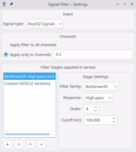
integer source. Be aware of the precision characteristics of float32.Channel selection
By default every channel of the incoming block is filtered. Alternatively, you can restrict filtering to a subset of channels by entering a comma-separated list of zero-based channel indices and ranges, for example:
0-15, 20, 24-31Channels that are not selected are passed through unchanged. Malformed tokens are ignored, and an empty selection means no channel is filtered (everything passes through).
Filter stages
A filter is built as an ordered chain of stages; the signal passes through each stage in turn. Each stage has a design family and, for the pole-filter families, a frequency response:
| Family | Description |
|---|---|
| Butterworth | Maximally flat passband. The sensible default. |
| Chebyshev I | Steeper roll-off at the cost of ripple in the passband (configurable passband ripple in dB). |
| Chebyshev II | Steeper roll-off with a flat passband, ripple in the stopband (configurable stopband attenuation in dB). |
| Notch (RBJ) | A 2nd-order Q-based notch, ideal for removing mains hum (50/60 Hz). Configured by center frequency and quality factor (Q). |
| Custom (SOS) | Raw second-order-sections you paste in directly (e.g. from scipy.signal), for arbitrary filter designs. |
For the Butterworth and Chebyshev families, the response can be Low-pass, High-pass, Band-pass or Band-stop. Low-/high-pass stages take a single cutoff frequency; band-pass/-stop stages take a center frequency and a band width. The filter order (1–12) controls the steepness of the roll-off.
All frequency-based families need to know the sampling rate of the signal. This is read from the
sample_rate metadata of the connected source. If the source does not advertise a sample rate, only
Custom (SOS) stages (whose coefficients already encode the rate) can be used; otherwise the run
will fail to start.
Cutoff and band frequencies must lie strictly between 0 Hz and the Nyquist frequency (half the sample rate), or the filter design is rejected.
Live changes
Both the channel selection and the filter chain can be changed while a run is in progress. Changes are applied at the next data-block boundary without interrupting the stream. If a live filter edit is invalid (for example, a transient out-of-range frequency while you are still typing), the previously valid filter keeps running and a warning is written to the log; the dialog flags the problem inline.
Note that the output stream metadata (see below) is fixed when the run starts, so channels added to or removed from the selection mid-run are not reflected in the recorded channel names.
Ports
The Signal Filter module exposes exactly one input and one output port, whose data type matches the selected input type. Only one of the following pairs exists at a time:
| Name | Direction | Data Type | Description |
|---|---|---|---|
| 🠺F32 Source | In | SignalBlockF32 | Float signal input |
| F32 Filtered🠺 | Out | SignalBlockF32 | Filtered float signal |
| 🠺I32 Source | In | SignalBlockI32 | Integer signal input |
| I32 Filtered🠺 | Out | SignalBlockI32 | Filtered integer signal |
| 🠺U16 Source | In | SignalBlockU16 | Unsigned 16-bit signal input |
| U16 Filtered🠺 | Out | SignalBlockU16 | Filtered unsigned 16-bit signal |
Stream Metadata
The output stream inherits the metadata of the input stream (so time_unit, data_unit,
signal_names, sample_rate and any data_scale / data_offset affine transform are carried
through — see common stream metadata), with two
changes that mark the data as filtered:
- The
signal_namesof channels that were selected for filtering at the start of the run are suffixed with_flt. - The proposed dataset name for recording is suffixed with
-filtered, so a recorded filtered stream is easy to tell apart from the raw one.
For frequency-based filter stages the input stream must advertise a sample_rate; without it the
run cannot start (Custom SOS stages excepted).